III.1. The detector's input optics and its directional sensitivity
Basically, the design of a detector's input optics is determined by its desired directional sensitivity, which in turn depends on the radiometric or photometric quantity to be measured:
• The determination of a light source's radiant and luminous flux requires constant directional sensitivity over the solid angle of 4π steradian or over the hemispherical solid angle of 2π steradian. This is achieved by an integrating sphere with the light source placed either inside the sphere or directly at the sphere's entrance port. Refer also to § III.1.b.
• The determination of irradiance and illuminance requires a detector's directional sensitivity proportional to the cosine of the angle of incidence, which can be achieved either by a flat field detector or by the entrance port of an integrating sphere. Refer also to § III.1.c.
• Radiant and luminous intensity, radiance and luminance are quantities which are defined as a function of solid angle, and therefore the detector's field of view has to be limited to a small angle. This can be achieved by baffles and/or lenses arranged in a tube. Refer also to § III.1.d and III.1.e.
III.1.a. Integrating spheres used with integral detectors
In an ideal case, the inner surface of an integrating is a perfect diffuse Lambertian reflector (see § II.4.c). Thus, the directional distribution of reflected radiation is independent from the directional distribution of incident radiation, and no specular reflection occurs. Due to its geometry, an ideal integrating sphere is characterised by constant irradiance (or illuminance) at all locations of it's inner surface. Furthermore, the level of this irradiance (illuminance solely depends on the total amount of radiant power (luminous flux) entering the sphere and is independent from its directional distribution.
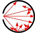
Fig. III.1. Ideal multiple Lambertian reflections inside an integrating sphere
However, real surfaces do not show perfect Lambertian reflection properties. Although minimised by the properties of the respective material, a certain amount of specular reflection still occurs. Baffles, placed at specific locations inside the sphere, are used to prevent major measurement errors by specular reflection. Moreover, at the input and exit ports, where the coating material is missing, radiation is far from being ideally reflected. For these reasons, the quality of measurements performed with integrating spheres strongly depends on the sphere's coating material, on the exact position of baffles and on the size of the ports in relation to the sphere's diameter. As a general rule of thumb, the total area of entrance and exit ports should not exceed 5% of the sphere's internal surface. Numerous standard setups are used for the determination of radiometric and photometric quantities, defining the arrangement of the sphere's entrance and exit ports and internal baffles (see § III.1.b. to III.1.f).
Apart from their directional sensitivity, integrating spheres offer additional advantages:
• The high number of internal reflections generally eliminates a detector's sensitivity to the polarisation of incident radiation.
• For the characterisation of powerful light sources, an integrating sphere can be used for attenuation in order to prevent saturation effects of the detector. As this attenuation results in an increase of internal temperature, the light source's maximum power is limited by the sphere's temperature range of operation.
• In general, geometric alignment of source and integrating sphere is not very critical, which simplifies calibration and measurement procedures.
For more detailed information about the theory and application of integrating spheres, see chapter V.
III.1.b. Measurement of radiant power and luminous flux
Radiant power and luminous flux of lasers and spot sources
Lasers, LEDs, spot lamps, endoscopes, optical fibres and other sources emit radiation with various directional distributions. As long the emission is limited to a hemispherical (2π steradian) solid angle, the source can be attached to the entrance window of an integrating sphere and does thus not interfere with the sphere's internal reflections.
The entrance port has to be large enough to ensure that all radiation from the source enters the sphere. A baffle is necessary to shield the detector from direct irradiation by the source.
Link to applicable product: PRW-0505 or LSM-9901 detector heads.
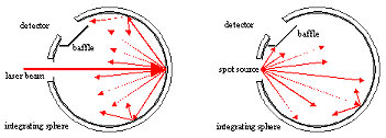
Fig. III.2. Integrating sphere used for laser power measurements (a) and radiant power and luminous flux measurements of spot sources (b).
As an alternative, radiant power and luminous flux of collimated (parallel) beams can be directly measured by flat field detectors as long as the detector's active area exceeds the beam's cross section. Despite the simple measurement setup, this method has significant disadvantages in comparison to the use of an integrating sphere:
• The detector might be possibly sensitive to the beam's polarisation.
• The detector's active area might be possibly inhomogeneous in its sensitivity. In this case, it is important to ensure equal illumination during calibration and measurement.
• Alignment of the detector relative to the beam is critical.
Link to applicable product: LP-9901 detector head.
Radiant power and luminous flux of lamps
Lamps emit radiation in all directions of the full (4π steradian) solid angle. Therefore, a lamp has to be placed inside an integrating sphere in order to determine its total radiant power or luminous flux. As a consequence, the lamp itself and its accessories interfere with the sphere's internally reflected radiation and thus causes a source of measurement error, which can be accounted for by use of an auxiliary lamp (see below).
Integrating spheres used to measure the radiant power or luminous flux of lamps must be well suited for the lamp under test to reduce measurement uncertainty. One important design parameter is that the diameter of the hollow sphere should be about twice the maximum dimension of the lamp. For example, an integrating sphere set-up to measure the luminous flux of fluorescent lamps with 120 cm (47 in) length should be at least 2 m (79 in) in diameter. Furthermore, the diameter of the sphere limits the maximum power of the lamp.
In actual measurements, the lamp must be placed in the centre of the hollow sphere. This is typically accomplished using a tube holder, which carries the power and measurement leads into the sphere. A socket at the end of the tube holds and connects the lamp. To get the lamp in the centre position, hinged integrating spheres that open and have large diameters of more than 50 cm (20 in) are used. Spheres with smaller diameters may offer a large diameter port to mount the lamp in the centre of the sphere. The port is normally closed with a cap during the measurement. The port cap‘s inside surface should be coated with the same diffuse coating as the hollow sphere surface. The detector is placed at a port on the integrating sphere. It must be baffled against direct irradiation by the lamp.
Link to applicable products: UM Integrating Spheres
Fig. III.3. Experimental setup for radiant power and luminous flux measurements of a lamp. The auxiliary lamp is used to reduce measurement errors caused by the interference of the lamp under test and its accessories with the sphere's internally reflected radiation.
For precise measurements, the lamp must be aged before testing. The burn-in time depends on the lamp type. The burn-in time for tungsten lamps should be 2-5 hours (IEC 64) and for arc lamps about 100 hours (IEC 81) is recommended.
In precise luminous flux measurement applications an auxiliary lamp with baffle(s) is recommended. The diffuse illumination generated by the auxiliary lamp can be used to reduce the negative effects of the lamp under test and its accessories according to the relation
ΦX : luminous flux of the test lamp
ΦN : luminous flux of the calibration lamp
YX : measurement signal of the test lamp (with auxiliary lamp switched off)
YN : measurement signal of the calibration lamp (with auxiliary lamp switched off)
YHN : measurement signal of the auxiliary lamp (with calibration lamp switched off)
YHX : measurement signal of the auxiliary lamp (with test lamp switched off)
III.1.c. Measurement of irradiance and illuminance
According to Equ.II.5 in paragraph II.4.e., a detector for irradiance or illuminance of a surface has to weight the incident radiation according to the cosine of its angle of incidence. This can be either achieved by
• an integrating sphere especially designed for irradiance (or illuminance) measurements (see figure below) or
• a cosine diffuser, an optical element which shows purely diffuse transmission regardless of the directional distribution of incident radiation (Fig. III.5).
In both cases, the ideal directional cosine response can only be approximately achieved. Deviations of a real detector's directional response from the ideal cosine response are quantified by the detector's cosine error function, which is given by
In this equation, S(θ) denotes the detector's signal caused by a ray of light impinging upon the detector's entrance optics at an angle θ, measured relative to the normal (see Fig. II.9). S(0) denotes the detector's signal caused by the same ray of light impinging vertically upon the detector's entrance optics.
Fig. III.4. Integrating sphere design for measurement of irradiance or illuminance of a horizontal surface. The baffle prevents direct illumination of the detector, and the knife edges at the sphere's entrance port prevent shading by the sphere's wall, which would distort the detector's cosine response.
Light Source |
Approximate Average Illuminance (lx) |
overcast night |
0,0001 |
full moon |
0,1 |
office light |
500 |
clear bright sky |
70000 - 85000 |
Table III.1 — Some average illuminance values
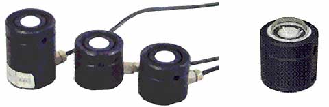
Fig. III.5 - Irradiance detector heads with cosine diffuser (a) and waterproof version for underwater and outdoor use (b)
Link to products: Illuminance / Irradiance Light Detectors
III.1.d. Measurement of radiant and luminous intensity
Radiant and luminous intensity describe the directional distribution of a source's emitted radiation. For determination of this directional distribution, the relative position between source and detector has to be varied. The goniophotometer is a mechanical setup allowing the variation of the source's orientation and/or the detector's position, whereby the distance between source and detector is kept constant. As the source's directional characteristics often depends on its internal temperature distribution and thus on its position relative to the vertical, for accurate measurements of radiant and luminous intensity it is not recommended to rotate the source around a horizontal axis.
As radiant and luminous intensity are defined by the surface integral of radiance and luminance (see Equ. II.4), the emitting source has to be completely in the detector's field of view. Ideally, both quantities have to be determined with a setup that allows the source to be considered point like. As a crude rule of thumb, the distance between detector and source should be at least ten times the largest geometric dimension of the source.
For precise measurements, special care has to be taken to minimize reflections at the lamp's surrounding (walls, ceiling, the goniophotometer itself) in the direction of the detector. Blackening of the surrounding, the use of additional baffles and the reduction of the detector's field of view are proper precautions.
Link to applicable products: Luminous Intensity / Radiant Intensity Detectors
III.1.e. Measurement of radiance and luminance
Radiance and luminance describe the directional distribution of the radiance emitted or reflected by a certain area element. Similar to radiant and luminous intensity, radiance and luminance can be determined with a goniophotometer, but the detector is placed much closer to the emitting or reflecting surface and the detector's field of view is limited to a few degrees. Thus, only radiation from a small part of the source's surface enters the detector (Fig. III.6).
Light Source |
Approximate Average Luminance (cd/m2) |
self-luminous paints |
0,02 10-3 |
Candle flame |
1 |
computer screen |
100 |
overcast daytime sky |
1000 |
clear bright sky |
5000-6000 |
Table III.2 — Some average luminance values
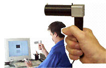
Fig. III.6. Gigahertz Optik's LDM-9901-4 Luminance Detector used to evaluate the contrast ratio of an LCD monitor.
Gigahertz Optik offers luminance detectors using achromatic lens systems to achieve a precise field of view, adjustable to 20', 1° and 6°.
Link to applicable products: Luminous Intensity / Radiant Intensity Detectors III.1.f. Measurement of reflection and transmission properties
Quantities such as reflectance and transmittance are used to describe the optical properties of materials (see § II.8).
• Reflectance ρ (for incident radiation of given spectral composition, polarization and geometrical distribution)
Ratio of the reflected radiant or luminous flux to the incident flux in the given conditions.
The measurement of reflectance is made in comparison to a reflection standard (reflectance ρN) with a collimated or conical radiation beam.
The signals of the detector will be calculated as follow:
I(X)-I(stray)
ρ = ------------------ ρN
I(N)— I(stray)
I(X): signal with sample irradiation
I(N): signal with standard irradiation
I(stray): signal with open measurement port
Fig. III.7. Integrating Sphere Total Reflection Measurement Set-up
• Diffuse Reflectance ρd
Ratio of the diffusely reflected part of the (whole) reflected flux, to the incident flux.
The measurement of diffuse reflectance is made in comparison to a reflection standard (reflectance ρN) with a collimated or conical radiation beam.
The signals of the detector will be calculated as follow:
I(X) - I(stray) - r [I(mi) - I(stray)]
rd = ----------------------------------------------- rN
I(N) - I(stray) - rN [I(mi) - I(stray)]
I(X): signal with sample irradiation
I(N): signal with standard irradiation
I(stray): signal with open measurement port
I(mi): signal with irradiance of a mirror
Fig. III.8. Integrating Sphere Diffuse Reflectance Measurement Set-up
• Transmittance t (for incident radiation of given spectral composition, polarization and geometrical distribution)
Ratio of the transmitted radiant or luminous flux to the incident flux in the given conditions.
The measurement of transmittance is made with a collimated or conical radiation beam. The signals of the detector will be calculated as follow:
t = I(X) / I(open)
I(X): signal with sample irradiation
I(open): signal with open measurement port
![]()
Fig. III.9. Integrating Sphere Total Transmittance Measurement Set-up
• Diffuse Transmittance td
Ratio of the diffusely transmitted part of the (whole) transmitted flux, to the incident flux.
The measurement of transmittance is made with a collimated or conical radiation beam. The signals of the detector will be calculated as follow:
I(X)- t.I(stray)
td = ---------------------
I(open)- I(stray)
I(X): signal with sample irradiation
I(open): signal with open measurement port and close output port
I(stray): signal with open measurement port and open output port
![]()
Fig. III.10. Integrating Sphere Diffuse Transmittance Measurement Set-up
Tutorials

Copyright © 2008 - 2025 Gigahertz-Optik, Inc. All Rights Reserved