VI.9. Nondestructive testing
The American Society for Nondestructive Testing defines NDT as the examination of an object with technology that does not affect the object's future usefulness. The term NDT includes many methods that can:
- Detect internal or external imperfections
- Determine structure, composition or material properties
- Measure geometric characteristics
Liquid Penetrant Testing (PT), Magnetic Particle Testing (MT) and Visual and Optical Testing (VI) are test methods used to detect defects in materials with the aid of optical radiation or light.
The light levels used in these operations are critical to the integrity of the inspection process so radiometric and photometric measurements are made for quality control purposes.
American Society for Testing and Materials (ASTM), MIL and DIN standard practices exist to help ensure uniformity in these examinations.
Liquid Penetrant Testing using the dye penetration examination process is a widely used method for the detection of surface defects in nonporous metal and non-metal materials. Two different methods are in use:
Dye Penetration Process:
A colored liquid or dye is applied to the surface of the test object which, through capillary action, penetrates into any existing surface defect(s). After removing any excess, an absorptive white layer is applied, drawing the colored liquid out of the defect making it visible. Adequate illumination of the test object with white light is critical to create good contrast.
Fluorescent Penetrating Agent:
For highest sensitivity, a fluorescent dye is used as the penetrating liquid and the test is carried out under ultraviolet lighting. UV-A sources known as 'blacklights' are most commonly used. To reliably test with fluorescent agents, an adequate level of UV-A irradiance containing a very low proportion of white (visible) light must be generated at the object under test.
Magnetic Particle Testing and of course Visual and Optical Testing both rely on ensuring adequate light levels for quality control of the examination.
DIN EN 1956, ASTM and MIL Standards exist that describe the general conditions and standard practices for the penetrant test examinations, including the procedures to be followed. The minimum requirements for the illumination or irradiation conditions, test procedures to be used for checking these levels and suitable measurement equipment specifications are also covered.
It is particularly emphasized in these standards that the calibration of the radiometer and photometer used to measure the illuminance and irradiance must be carried out with the aid of calibration standards that can be traced back to national standards. The test certificate must document the calibration testing.
The calibration method must also be considered.
Many of the UV-A radiometers used in this application are calibrated at a single point at the peak of the detector spectral response, typically 360 nm or simply adjusted to some reading on a particular light source. To reduce measurement errors due to light sources with different spectral outputs, Gigahertz-Optik uses the integral calibration method where the detector is calibrated to a measured UV-A integrated spectral irradiance standard.
To reduce spectral errors even further, the Gigahertz-Optik UV-A detector exhibits a nearly flat response across the UV-A bandpass with a sharp cut-off at 400 nm to eliminate visible stray light from contaminating the UV reading.
The spectral response function of the photometric sensor is very important for the same reasons. Spectral errors when measuring lux or foot-candles can occur when testing light sources different from the source used for calibration. A detector that very closely matches the CIE photopic function is required for accurate photometry. The Gigahertz-Optik photopic sensor's spectral function is within DIN Class B limits of <6% fidelity to the CIE photopic curve.
The detector spatial response (angular response) is another important factor and potential error source.
Since the detector is fully immersed in light from all directions, including any ambient contribution, it should be cosine corrected, using a diffuser. This way the incoming light signals are properly weighted according to the cosine of the incident angle. The detector receives the light signals in the same way as a flat surface does, so in effect the detector emulates the sample under test. If the detector spatial response does not closely match the true cosine function, significant errors in readings will result.
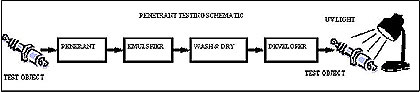
Fig. V.23. Penetrant Testing Schematic
UV sources pose a potential health hazard risk to the skin and eye. UV-A sources used in PT emit some levels of the most harmful UV-C and UV-B rays. The UV-A rays are considered less of a risk, but the ACGIH/ICNIRP guidelines do state Threshold Limit Values for UV-A at 1 mW/cm² for an eight-hour exposure period. For UV-B, the TLV is much less at 0.1 Effective W/cm². So UV exposure of workers in PT environments should be tested to ensure safety as well as for quality control.
Tutorials
Copyright © 2008 - 2025 Gigahertz-Optik, Inc. All Rights Reserved