III. 5. Calibration of integral Detectors
Calibration is the determination of the correlation between an input and an output quantity. All measurement instruments, such as voltmeters, manometers, vernier calipers, etc., must be calibrated to determine the variation in reading from the absolute quantity. In radiometry, the input quantity is provided by standard lamps and optical radiation detector standards. Because of the many different measurement quantities involved, calibration standards for each quantity are required if an optical radiation calibration laboratory hopes to cover the whole range of possible calibrations. A 'traceable' lab calibration standard should show an unbroken chain of links to national (better international) standards. But this in itself does not guarantee accuracy or the ability of the lab to meet its calibration uncertainty claims. Since calibration standards are subject to change with age and use, a means to periodically check the calibration of the standards themselves must be in place. Occasionally the standards must be replaced in order to maintain the quality of calibration and traceability. The end user of the calibrated product may be required to audit the calibration facility to ensure its competency and traceability. In Germany, the Deutsche Kalibrierdienst — DKD (the German accreditation institution) and the Physikalisch-Technische Bundesanstalt (the German national standard laboratory) offer an accreditation service for industrial calibration laboratories where the lab's calibration standards, calibration procedures and the stated re-calibration intervals are subject to audit. This accreditation ensures that the traceability of the calibration is on an absolute level. The DKD also ensures the international acceptance of its accredited calibration laboratories. Refer to Appendix VI.6 for more information on national calibration organizations.

Fig. III.14. GO Calibration Engineer
III.5.a Traceability: an Unbroken Chain of Transfer Comparisons
Calibration is the most important prerequisite for accuracy in measurement instrumentation. It is the foundation upon which subsequent measurements are based upon. Optical radiation calibration is typically done by the transfer method where the relationship between the value indicated by a measuring instrument and the value represented by a calibration standard is compared with the former reading adjusted as needed, recorded and certified. Since the reading of a meter-under-test is directly compared against that of the transfer standard, the qualification of this standard is of the highest importance. A qualified standard should display an unbroken chain of transfer comparisons originating at a national standards laboratory. For example, the transfer standard of the national laboratory, primary standard (A) is used to calibrate the reference standard (B) at an accredited calibration laboratory. This reference standard is used to calibrate the laboratory work standard (C) to be used daily by the cal lab. This work standard is then used to calibrate the final product (D) or device under test. Accordingly, the calibration path is A-B-C-D. This path is called the chain of traceability. Each transfer device in the chain should be subjected to periodic examination to ensure its long-term stability. The lab performing the calibration typically sets the time span between examinations and is self audited.
Fig. III.15 - Calibration Hierarchy from Primary Standard to Test Equipment
Accredited calibration laboratories guarantee recalibration cycle times for their standards plus a review of their calibration procedures since they are subject to review by an official accreditation authority.
Link to products: Calibration Services
Fig. III.16 - Hierarchy of Standards
III.5.b. ISO/IEC/EN 17025 (formerly ISO Guide 25 and EN45001)
The aims of the General Requirements for the Competence of Calibration and Testing Laboratories are to provide a basis for use by accreditation bodies in assessing competence of laboratories; establish general requirements for demonstrating laboratory compliance to carry out specific calibrations or test; and assist in the development and implementation of a laboratory's quality system. * Without exception, DKD accredited calibration laboratories fulfill the requirements of the European standard EN 45001 (general criteria to operate a testing laboratory, May 1990). Outside of Europe this standard is not compulsory. Instead of this the ISO/IEC Guide 25 (General requirements on the competence of testing and calibration laboratories, December 1990) is recognized. In content, EN 45001 and ISO/IEC Guide 25, known as ANSI/NCSL Z540-1 in the United States, is identical. This is the basis for the mutual appreciation between the European cooperation for Accreditation (EA) and its extra-European partners. In 1999 ISO/IEC 17025 took the place of EN 45001 and ISO/IEC Guide 25 which eliminated any formal differences.
ISO/IEC/EN 17025 is compatible with A2LA and NVLAP requirements. *ISO 17025 web page : www.fasor.com
III.5.c Calibration Quantities
Spectral Irradiance — W cm-2 nm-1 Irradiance (W/m2) measured as a function of wavelength (nm), is known as spectral irradiance. This type of source calibration is performed with a spectral measurement device or spectroradiometer as compared to a reference standard. The spectral range of calibration depends on the source and spectral zone of interest. A typical QH lamp may be spectrally scanned from 200 to 2500 nm using a fixed wavelength increment or variable bandwidth depending on the required resolution.
Spectral Radiance — W cm-2 sr-1 nm-1 Radiance (W/cm2·sr) measured as function of wavelength is called spectral radiance. Radiance in a given direction, at a given point of a real or imaginary surface is the optical unit used to calibrate optical radiation sources. Calibration is normally performed with a spectral measurement system or spectroradiometer equipped with a radiance lens assembly that has been calibrated with an integrating sphere based radiance standard. The spectral range of calibration will depend on the source and the spectral range of interest. A full spectral scan may cover from 350 to 2500 nm.
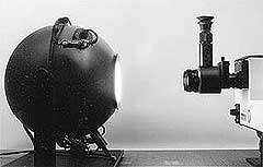
Fig. III.17. Spectral Radiance Calibration
Spectral Responsivity Optical radiation detectors, photodetectors, photodiodes, exhibit changes in sensitivity at different wavelengths. This spectral responsivity can be measured as relative responsivity in percent (%) versus wavelength (nm) across the active wavelength bandpass of the photo-device. For example a silicon device scan could cover the wavelength range from 250 to 1100 nm at a set increment. Or a GaAsP photodiode from 250 to 700 nm. The increment setting could span from 1 to 50 nm depending on the required resolution. Also, single point response at a particular wavelength may be all that's required for some applications. Calibrations are performed by transfer comparison and certified against qualified reference standards.
Fig. III.18. InGaAs Detector Relative Spectral Response Plot
Illuminance Sensitivity — lux / foot-candles Calibration of the illuminance response of photopic detectors is normally performed as a transfer comparison from a photopic reference standard. The photometric responsivity of the reference standard can be qualified through radiometric measurement using red, blue and green filtered photodetectors. However this is a complicated procedure left to advance radiometry labs. Illuminance sensitivity calibrations allow direct reading of the photopically corrected detector in lux or foot-candles. Very often a tungsten source is used for illuminance calibrations. If the photopic detector spectral response does not match the CIE photopic curve too a high degree, measurement errors will occur when measuring different type sources.
Fig. III.19. CIE Photopic Function
Luminance Sensitivity — cd/m2 & fL Luminance responsivity of photopic detectors equipped with field limiting input optics is accomplished by comparison to a luminance reference standard detector. A uniform field of luminance is produced as the calibration source using an integrating sphere or a source with an optically diffuse material in front of it. Luminance detector's field of view is confined to a narrow angle so that the detection area is overfilled with a sample of the uniform luminance field. Luminance detectors are calibrated to measure in the optical units of candela per square meter and foot-lamberts.
Color Sensitivity Broadband colorimetric detectors are calibrated by comparison to reference standards based on CIE tristimulus values using a light source of known color temperature. Color temperature, luminance and illuminance calibrations may be included depending on the color meters capability. The color meter is calibrated to display the color chromaticity coordinates x,y and /or u', v' of the light source under test.
Fig. III.20. Color Detector Tristimulus Functions
Irradiance Sensitivity — W/m2 & W/cm2 Broadband irradiance detector calibrations are performed by transfer comparison to reference standards with consideration to the spectral characteristics of the detector to be tested. Reference detectors are calibrated against spectral irradiance measurements using a double monochromator spectroradiometer, itself calibrated using traceable spectral irradiance standards. Irradiance detectors are calibrated to read out in the optical units of watts per square meter or watts per square centimeter over a specific wavelength range.
Fig. III.21. BLUE Spectral Response Irradiance Detector
Spectral Reflectance Calibration of the spectral reflectance of materials is accomplished by comparison to reference reflectance standards which themselves are used to set-up calibration of the spectrophotometric instrument which actually performs the measurement. Single or double beam spectrophotometers can spectrally range from 250 to 2500 nm, with adjustable wavelength increments. When coupled to an integrating sphere; total hemispherical, diffuse and specular reflectance can be separately measured with the spectrophotometer. Without the sphere the in-line set-up of the spectrophotometer measures the normal specular reflectance component only.
Fig. III.22. 8 Degree Reflectance Measurement Set-up
Spectral Transmittance Calibration of the spectral transmittance of materials is accomplished by comparison to reference transmission standards which themselves are used to set-up calibration of the spectrophotometric instrument which actually performs the measurement. Single or double beam spectrophotometers can spectrally range from 250 to 2500 nm, with adjustable wavelength increments. When coupled to an integrating sphere; total hemispherical, diffuse and regular (specular) transmittance can be separately measured with the spectrophotometer. Without the sphere the in-line set-up of the spectrophotometer measures the regular reflectance component only. Calibration is performed as percent transmission versus wavelength.
![]()
Fig. III.23. Transmission Measurement Set-up
III.5.d Calibration Standards
Calibration standards are employed to generate an input quantity for the equipment used in the calibration. Since the calibration standard supplies a signal of known quantity, the difference of the output signal of the equipment to the signal of the calibration standard can be evaluated. From these differences calibration correction factors can be calculated allowing absolute readings when the output signal is corrected by these values. For photometric and radiometric measurement quantities different calibration standards are needed: Photometric — Radiometric Quantity:
• Luminous Flux — Radiant Power
• Luminous Intensity — Radiant Intensity
• Luminance — Radiance
• Illuminance — Irradiance
Equivalent photometric and radiometric quantities exist where the measurement and therefore calibration geometry is the same. The only difference is the radiometric or photometric responsivity of the detection system. This means most calibration reference standards can be used for both, photometric and radiometric calibration, if the calibration data is available. For very precise or close tolerance calibrations specially selected calibration standards are needed. Typically calibration standards are used as transfer standards, meaning they transfer the values of the primary standard to a lab standard for subsequent transfer to a device under test. For traceable calibrations an unbroken chain of transfer comparisons back to the national primary standard is certified. Calibration uncertainty is of course dependent on the calibration hierarchy of the standard. Since the calibration transfer is a real hardware transfer of the standard itself, careful handling and operation of the calibration standard is extremely important. In imaging applications the uniformity of response or transmittance is critical. So light sources with a uniform luminous area are needed to determine the non-uniformity of a lens system or visual imaging detection system
Source Based Standards
Every optical radiation detection or measurement system needs to be calibrated in reference to an optical radiation source. There are two possible ways to handle the calibration:
• The source may be calibrated in the required quantity and the difference between the input signal, generated by the source, and the output signal of the detection system can be determined using the calibration data of the source
• The uncalibrated source may be operated under stable conditions and the calibration done by comparing the reading of the detection system with a calibrated detection system (reference standard). The reference standard must have the same measurement geometry and the same spectral response as the unit to be calibrated.
The most common optical radiation source used for calibration standards is the tungsten halogen lamp since its emission spectrum is close to a Planckian radiator (blackbody source). Other sources where optical radiation is produced by means of an element heated to incandescence by electrical current are also in use. Filament position and stability of the tungsten halogen lamp is critical plus it has a limited lifetime. Therefore the lamp should only be operated in the position specified in the calibration certificate. Comparing the lamp output against other in-house reference standard sources or against suitable reference detection systems must be periodically done to check stated lamp calibration uncertainty. In radiometric applications, where the spectral characteristic of the source is used, the source should be operated in current controlled mode, to ensure the stability of the spectral characteristic. The minimum specification for current stability should be held at 10-4 A. In photometric applications or radiometric applications with broadband detectors, intensity controllable standards can be used if changes in the spectral emission characteristics are not critical. If the tungsten halogen lamp is used as a spot source the exact location on the filament used during the calibration of the source, must be subsequently used. In luminance, radiance and imaging uniformity calibrations, tungsten halogen lamps must be fitted with a diffuse screen or placed within an integrating sphere. Sphere based luminance and radiance standards offer higher uniformity and a better diffuse function.
Fig. III.24. Diffuse Screen & Integrating Sphere
For calibrating luminance and radiance meters with a limited field-of-view, a diffuse transmitting screen can be used at the sphere output. In imaging applications the uniformity and the diffuse function of currently available screen materials are not precise enough so the open output port of the sphere is typically used. If the intensity of the tungsten halogen lamp is not high enough, which happens especially in the UV range, arc lamps such as xenon lamps may be used. But the increase in intensity can affect calibration uncertainty.
Detector Based Standards
Due to the high levels of maintenance and care required to operate optical radiation source based calibration standards, detector based standards are very attractive alternatives. The detector has the advantage of long-term absolute and mechanical stability, especially true of semiconductor detectors. The use of detector-based standards is very common in monochromatic radiometric applications such as the calibration of laser power meters for telecommunication testing. But because of surface reflections, polarization effects, beam misalignment and beam 'bounce-back' errors, the use of detector based calibration standards must be carefully considered. The use of spectrally broadband detectors as calibration standards is mostly limited to photometric applications where detectors with a precise filter corrected photometric spectral response are available. Calibration is performed by comparison of the output signal of the reference detector to that of the device to be calibrated. The same stable source of optical radiation is used during the calibration procedure. For monochromatic calibrations a monochromatic radiation source is needed. If a detector's spectral responsivity is to be measured over its entire active bandpass, a tungsten halogen lamp with a monchromator attached to it can be used to create monochromatic radiation at all of the different required wavelengths.
Spectral Irradiance Standards
Tungsten Halogen lamps are the 'workhorse' of spectral irradiance standards. FEL type lamps with a filament support arm are recommended for high intensity BLUE light and UV applications.
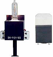
Fig. III.25. FEL Calibration Standard Lamp
Sylvania calibration grade lamps are recommended for visible and near IR applications where the best long term stability is required. In order to qualify for calibration as a standard, each lamp must undergo a minimum 15-hour burn-in procedure and must display a satisfactory burn-in data trend during this period. The calibrated tungsten reference source provides spectral irradiance data from 250 to 2500 nm covering many typical UV-Vis-IR radiometric and photometric applications. The lamp is normally provided in a housing and socket made from ceramic or other material which ensures long-term stability and protection. Filament targeting aids may be provided for best measurement accuracy in the calibration laboratory. Since lifetime is somewhat limited, lamp power supplies with on/off ramping functions are recommended for use with these sources.
Fig. III.26. Lamp Spectral Distribution
Luminance Standards Reference sources of luminance are used to calibrate the uniformity of imaging systems and the luminance output of luminance meters, spot exposure meters and other photometric equipment.
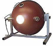
Fig. III.27. Luminance Standard
The standard is constructed around the integrating sphere of various diameters which provide the highly uniform diffuse luminance at the exit port required for these types of calibrations. The spheres may be coated with barium sulfate or machined from optically diffuse plastics. Seasoned tungsten halogen sources are typically used with lamp power supplies and temperature stabilized photometric reference detectors to form the complete system. Control feedback loop techniques control the luminance output intensity and help prolong the useable lifetime of the system. Any change in ambient and sphere body temperature affecting the output signal is eliminated through the temperature stabilized reference detector. This also reduces system warm-up time. An optimally designed sphere layout is capable of less than ± 0.7% non-uniformity over 90% the port opening which can be as large as 100 mm in diameter. Angular uniformity of less than ± 5% within ±40° enables luminance output calibration of detection systems with wide acceptance angles. Luminance outputs can range from 0.5 to 35000 cd/m2. Some standards may offer a variable luminance output requiring more sophisticated electronics, multiple lamps and exhaust fans. In order to qualify as a calibration standard the system itself must be calibrated by a competent calibration facility. Luminance output, uniformity and angular uniformity must be measured and certified.
Fig. III.28. Typical Luminance Uniformity Response Plot
Spectral Radiance Standards
Reference sources of radiance are used to calibrate radiance detectors and other radiometric equipment. The standard is constructed around the integrating sphere of various diameters which provide the highly uniform diffuse radiance at the exit port required for these types of calibrations.
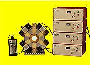
Fig. III.29. Variable Radiance Standard
The spheres may be coated with barium sulfate or machined from optically diffuse plastics. Seasoned tungsten halogen sources are typically used with lamp power supplies and temperature stabilized photometric reference detectors to form the complete system. Control feedback loop techniques control the luminance output intensity and help prolong the useable lifetime of the system. Any change in ambient and sphere body temperature affecting the output signal is eliminated through the temperature stabilized reference detector. This also reduces system warm-up time. An optimally designed sphere layout is capable of less than ± 0.7% non-uniformity over 90% the port opening which can be as large as 100 mm in diameter. Angular uniformity of less than ± 5% within ±40° enables luminance output calibration of detection systems with wide acceptance angles. Some standards may offer a variable radiance output requiring more sophisticated electronics, multiple lamps and exhaust fans. In order to qualify as a calibration standard the system itself must be calibrated by a competent calibration facility. Radiance output, uniformity and angular uniformity must be measured and certified.
Fig. III.30. Typical Spectral Radiance Plot
Spectral Responsivity Standards
Due to their long term stability and broad spectral coverage, silicon photodiodes are used as reference spectral standards by national and private calibration laboratories worldwide.
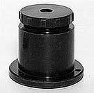
Fig. III.31. Detector Calibration Standard
These photodiodes with active areas as large as 100 mm2, are mounted into machined housings to protect and precisely fix the detector in a calibration set-up in concert with targeting aids. Some housings may include an integral temperature sensor to monitor thermal characteristics during test sessions. Or to ensure best measurement uncertainty, temperature stabilization using cooling jackets that maintain the device temperature to within ± 0.5°C are employed. UV enhanced Si devices offer spectral coverage from 250 to >1100 nm. Calibration with certification from an accredited traceable calibration facility is required to qualify the device for use as a reference standard.
Fig. III.32. Typical Spectral Responsivity Plot of Si PTD
Reflectance Standards
White optically diffuse reflectance standards traceably calibrated for spectral reflectance over a spectral range from 250 to 2500 nm are used in the calibration of reflectance meters, optical distance measurement systems, densitometers, spectrophotometers and other optical and imaging systems. Qualifications of a reflectance standard include light and temperature stability and durability, near Lambertian diffuse reflectance and up to 98% spectrally neutral reflectance over the spectral range of interest. Processed PTFE machined and cut into various shapes and thicknesses is currently used for reflectance standards. High reflectance white, black and gray shades at varying reflectance values are available.
To maintain the quality of a calibrated standard it is normally mounted into a protective housing with a removable lid to keep the material clean and covered when not in use.

Fig. III.33. Optically Diffuse Reflectance Standards
Link to products: Calibration Standards
Gigahertz-Optik
Calibration Standards & Calibration Services
Traceable calibrated reference lamps, detectors and reflectors for the calibration and adjustment of sensors and measurement devices for light, optical radiation and light reflection.
Find product information here.
Calibration Laboratory
The calibration laboratory of Gigahertz-Optik GmbH Traceability, thanks to DAkkS* certification
See Gigahertz-Optik's Calibration Laboratory here.
Interested in discussing your calibration requirements?
Give us a call!
Copyright © 2008 - 2025 Gigahertz-Optik, Inc. All Rights Reserved